Solutions

SVG solution for off grid operation of PV Solar-storage microgrid
1. Technical background and application scenario
Driven by the global decarbonization strategy and accelerated deployment of Business Energy Storage (BESS), high energy consuming heavy industrial manufacturing, such as blast furnace smelting, non-ferrous metal refining, chemical manufacturing, and large-scale mining beneficiation plants, are introducing distributed PV power generation systems and configuring large capacity BESS on a large scale.
There are generally high-power inductive loads, high impact start stop currents, and complex power electronic harmonic waveforms inside such heavy industrial facilities. The integration of high penetration photovoltaic and BESS has transformed the distribution network of traditional factories into an industrial microgrid system that combines grid connected and independent off grid operation capabilities. In order to ensure the continuity of the production line, the system must have extremely high transient and steady-state power quality control capabilities.

2. Technical requirements for reactive power compensation equipment under off grid conditions
When industrial microgrids suddenly switch from high inertia public power grids to low inertia "photovoltaic+energy storage" independent isolated network topologies, the short-circuit capacity, fault level, and transient stability margin of the system will undergo drastic changes. This dynamic crossover across all operating conditions imposes the following three non-traditional rigid technical requirements on reactive power compensation equipment:
a. Capable of bidirectional infinite continuous adjustment in four quadrants
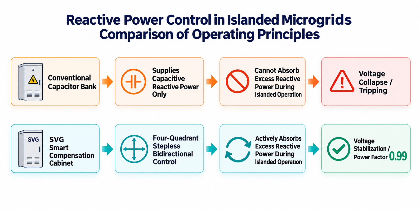
Modern reactive power compensation equipment must break the limitations of traditional "only outputting capacitive reactive power" and must have four quadrant working ability, capable of bidirectional, linear, and infinite continuous adjustment. When off grid overcompensation occurs, the device must be able to reverse switch from "output capacitive reactive power" to "actively absorb capacitive reactive power (i.e. output inductive reactive power)" within milliseconds. Thus, it completely eliminates the excess capacitive reactive power in the system and protects the energy storage inverter (PCS) from the threat of overvoltage tripping.
b. It has a transient response speed in milliseconds (ms)
The reactive power compensation scheme must adopt high-frequency switch control technology of all power electronic devices. The transient response time of the system must be within 1 millisecond, and the full cycle response time must be less than 10 milliseconds. During dynamic transient moments such as mode switching or load changes, achieve instantaneous infinite following regulation, suppress voltage flicker, and prevent instantaneous voltage collapse in microgrids.
c. Possess constant current source characteristics, independent of system voltage fluctuations
The reactive power output capacity of traditional capacitive compensation equipment is extremely dependent on the grid voltage and is directly proportional to the square of the voltage (Q=ω C U ²). At critical moments when the bus voltage drops significantly due to off grid switching or heavy load switching, traditional capacitors will experience exponential degradation in compensation capability due to voltage drop, and fail when the system needs reactive power support the most.
Low inertia microgrids require compensation hardware with constant current source output characteristics. Even if the bus voltage drops sharply due to transient impact, the equipment can still maintain the rated full load reactive current output, providing strong voltage support for the microgrid and preventing cascading power outages.
3. Conventional capacitor compensation cabinet (TSC) fails in this scenario
Control blind spot: The sampling transformer (CT) of traditional capacitor controllers is usually deployed on the main incoming line side of the mains power. After the power outage, the sampling current returned to zero, causing the controller to become blind and unable to correctly command the capacitor to exit.
Response lag: Traditional capacitors have a minute level discharge dead time after removal, which cannot meet the millisecond level (ms) transient stability requirements of isolated microgrids.
4. Solution and Configuration
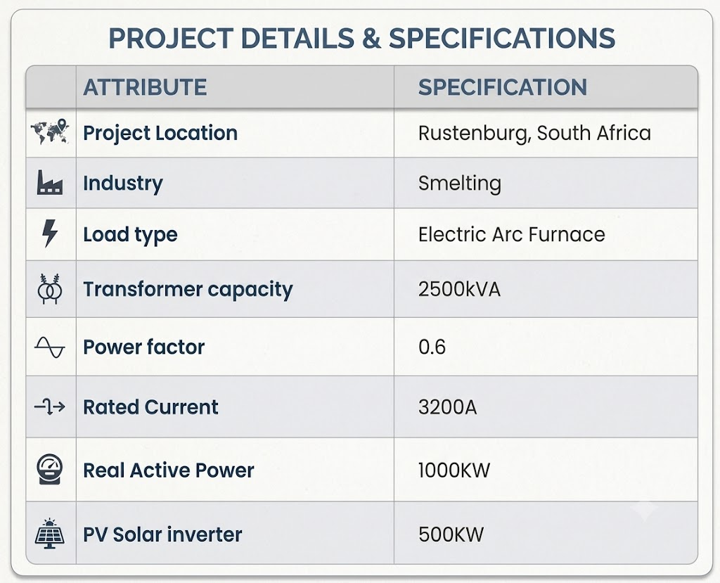

Power Quality Audit Report
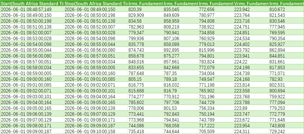
This case has already been equipped with an 800kVar capacitor compensation cabinet with 7% reactor, adopting an integrated upgrade mode of "completely dismantling old capacitors and fully configuring a new SVG intelligent compensation cabinet.
Dismantle the original reactive power compensation capacitor cabinet and install 2 units of Floor stand Sinava SNA-SVG-F500 SVG cabinet switched by IGBT
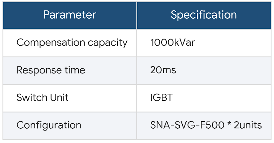
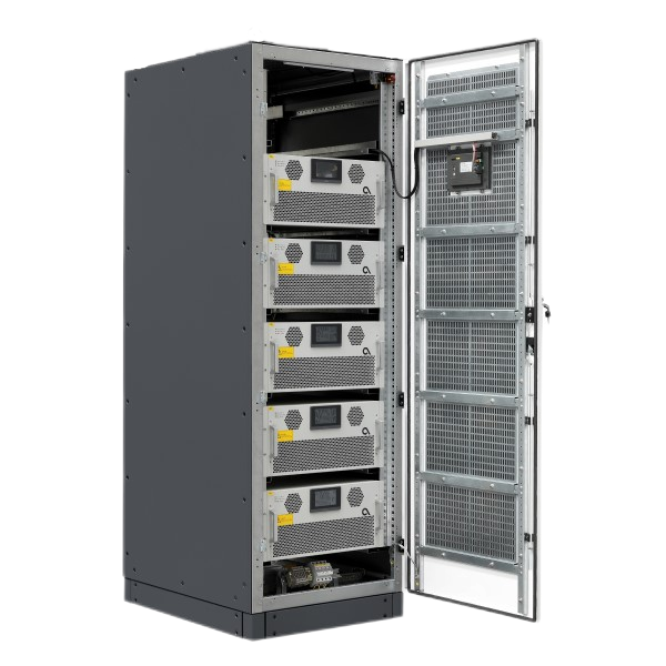
When the external public power grid unexpectedly loses power and the system switches to "photovoltaic+energy storage" off grid operation, the SVG cabinet immediately becomes the local voltage and power factor stability center of the microgrid. Through its four quadrant bidirectional dynamic adjustment capability, the network control system of SVG cabinet and energy storage PCS is highly coordinated. When transient capacitive flooding occurs within the microgrid due to sudden load drops or a surge in new energy, the SVG cabinet can actively absorb capacitive reactive power within 10 milliseconds. Prior to triggering overvoltage protection in the energy storage PCS inverter, this ensures safe hedging and smoothing of the reverse reverse reactive current, stabilizing the power factor above 0.95 in the isolated grid state. The fluctuation of the microgrid bus voltage is controlled within an extremely low range of less than 2%, truly guaranteeing the uninterrupted green operation of heavy industry factories under frequent power outages or power restrictions in the power grid.




Please leave us your messages and feedback, our sales engineers are always right beside you.

