Solutions

Active Harmonic Filter (AHF) Application in a Hong Kong Hospital Power Distribution System
Two-level harmonic mitigation: bus-level and critical-load-level filtering
1. Design Basis and Distribution Structure of a Large Hospital
The design basis of this project mainly referenced the Electrical and Mechanical Services Department (EMSD) Code of Conduct for the Electricity (Lines) Regulations, the Hospital Authority (HA) hospital engineering design standards and Electrical Installation Design Standard Checklist, together with the relevant electrical technical specifications of the Architectural Services Department (ArchSD) and the supply rules of the local power company.
For a large hospital, the typical power supply structure can be understood as:
11 kV / 22 kV medium voltage → MV switchgear → distribution transformers → 380/220 V LV main distribution → functional busbars → medical and building loads
In actual projects, the MV level, the number and capacity of transformers, the LV busbar sections, and the backup power arrangement must be confirmed against the hospital's actual supply conditions and load profile.
A key feature of this project is the use of relatively independent LV busbars for different functional areas. In particular, radiation-related loads do not share a busbar with other critical medical loads. The AHF design must therefore consider each distribution area separately.
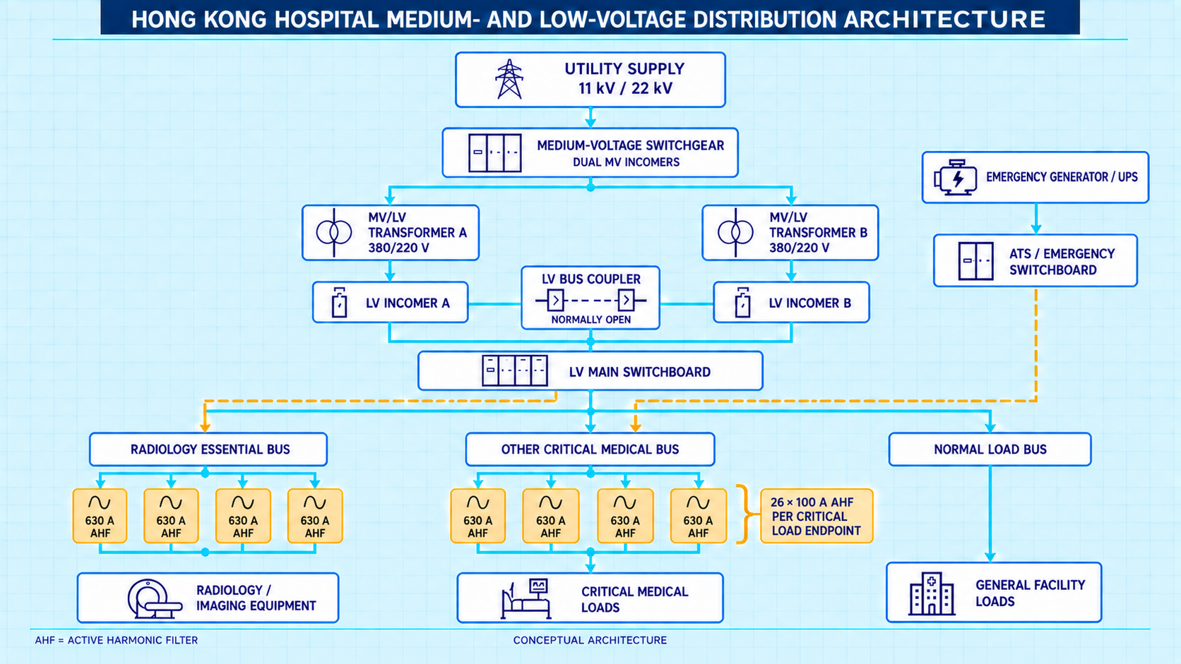
Figure 1. Conceptual MV/LV distribution architecture of a large hospital (AHF = active harmonic filter).
2. Power Quality Challenges in Hospital LV Systems
Modern hospitals contain a large number of power-electronic devices, which are also significant sources of harmonic currents. The rectifier stage of UPS systems, medical imaging equipment such as CT and MRI, X-ray systems, variable-frequency air-conditioning drives, IT equipment, and LED lighting can all generate harmonics to varying degrees.
These harmonics first appear in the feeders where the loads are connected. When multiple nonlinear loads operate simultaneously, the harmonic currents converge upstream and eventually form a combined harmonic load at the LV bus level.
Harmonic problems in hospitals therefore typically exist on two levels at the same time:
To protect critical equipment and resolve bus-level distortion, this project adopts a two-tier mitigation solution.
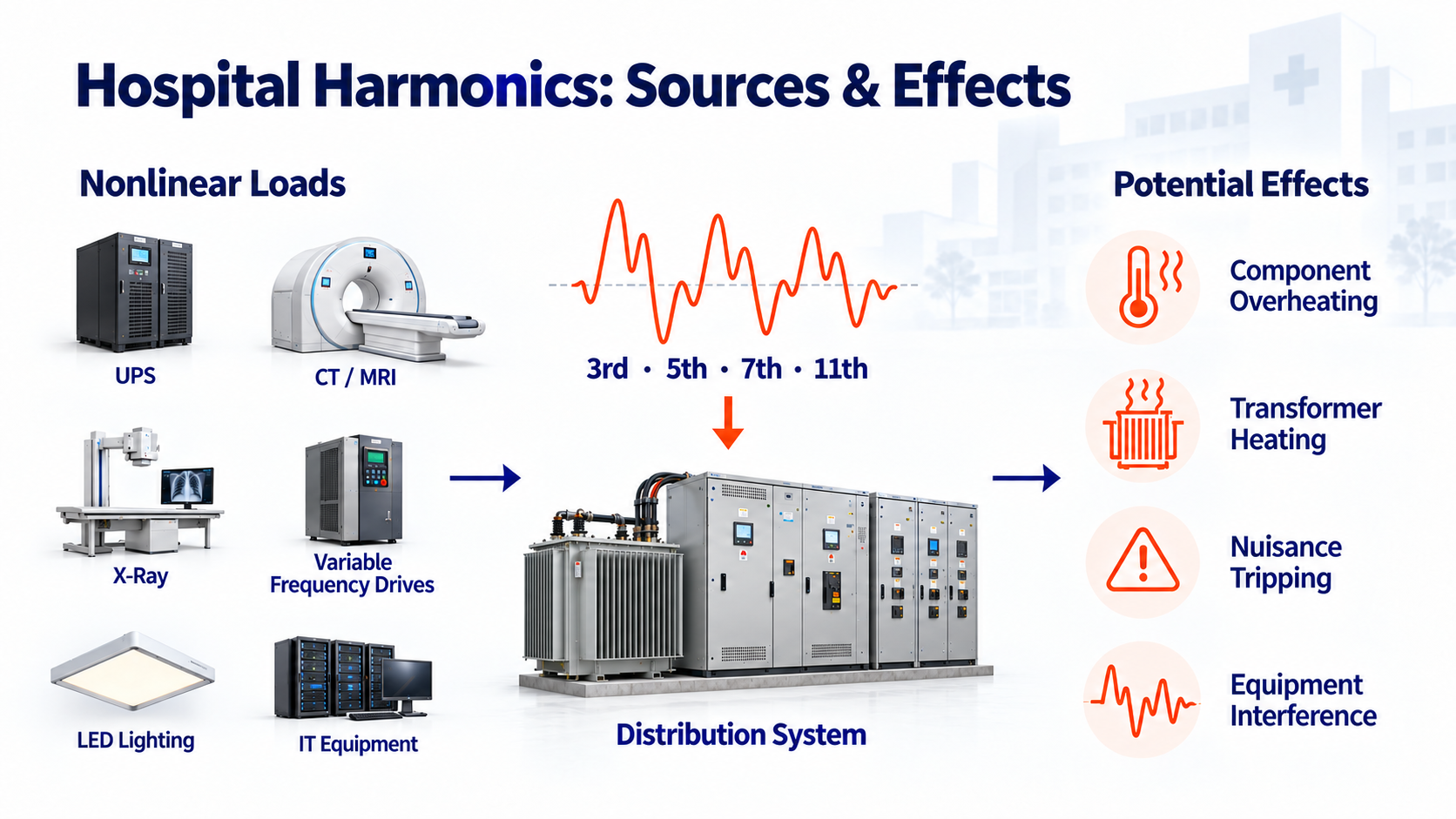
Figure 2. Common harmonic sources in hospitals and their potential effects (3rd, 5th, 7th, 11th harmonics; component overheating, transformer heating, nuisance tripping, equipment interference).
3. Overall AHF Configuration
This project is equipped with a total of 34 AHF units, distributed as follows:
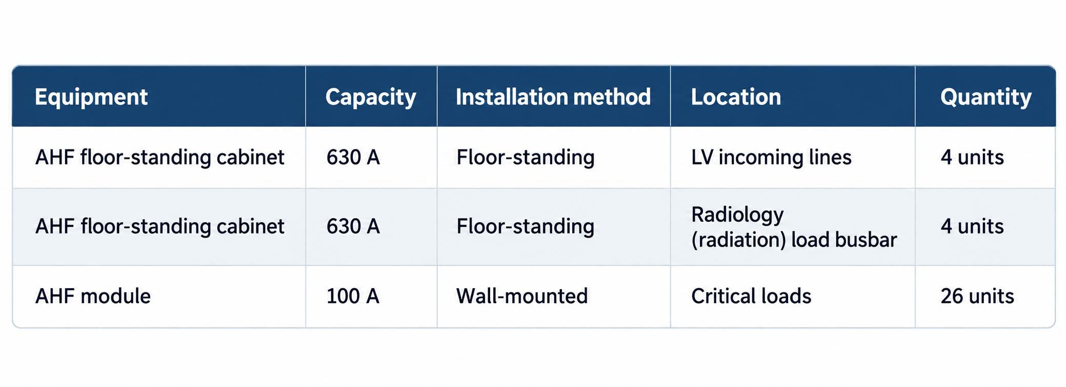
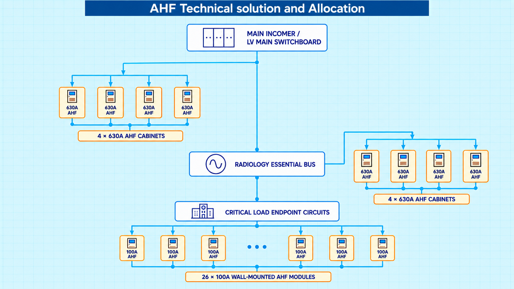
In other words, the project combines eight 630 A cabinet-type AHFs — four at the low-voltage incoming lines and four at the independent radiology busbar — with twenty-six 100 A wall-mounted AHF modules near critical loads. The eight 630 A units are installed at different LV incoming-line or functional-busbar positions, each responsible for harmonic mitigation in its own distribution area. Because the hospital's radiation busbar is independent of the other critical load buses, its 630 A AHFs are configured separately.
Overall, this project uses multiple independent bus-level AHF systems rather than a single central filter.
4. Bus-Level Harmonic Mitigation (630 A)
The eight 630 A cabinet-type AHF units are mainly responsible for comprehensive harmonic control of the LV incoming lines and the main functional busbars.
A single hospital LV busbar may feed UPS systems, medical imaging equipment, variable-frequency drives, IT equipment, and other nonlinear loads. The harmonics generated by any single device may be modest, but when many devices operate simultaneously the harmonic currents accumulate on the busbar.
A 630 A AHF installed at the corresponding incoming line or busbar dynamically compensates for the combined harmonic current of that distribution area. Note that 630 A is the maximum compensation current rating of the AHF — it does not mean there is 630 A of harmonic current on the bus, nor that the AHF must carry the entire bus load current.
Each 630 A AHF is therefore responsible for the comprehensive harmonic management of one distribution area.
5. Load-Level Mitigation for Critical Loads (100 A)
The 26 wall-mounted 100 A AHF units are installed close to critical medical equipment and their feeders.
Equipment such as CT scanners, X-ray machines, MRI systems, and UPS units typically exhibits strong nonlinear characteristics. If the harmonics generated by these devices were allowed to propagate down the feeder to the next distribution cabinet before being treated, they would already have travelled through a considerable amount of cabling and equipment.
This project therefore places each 100 A AHF as close to its critical load as possible. When a medical device generates significant harmonic current during operation, an AHF mounted near its feeder compensates the harmonics locally, reducing propagation into the upstream distribution system.
The principle can be summarized in one sentence: harmonics should be mitigated where they are generated. This improves the local power quality and reduces the harmonic current the upstream bus has to handle.
6. Why Two Levels: 630 A and 100 A?
The two AHF ratings occupy different electrical positions and handle harmonics at different levels of the distribution hierarchy:
Critical load → 100 A AHF → LV busbar → 630 A AHF → upstream distribution system
The 100 A AHFs, located near the critical loads, deal with locally generated harmonics first. The remaining harmonics flow to the next busbar, where the 630 A AHFs treat the combined distortion.
This is a tiered mitigation approach — and the main reason the project uses 34 AHF units of different capacities instead of one large central AHF.
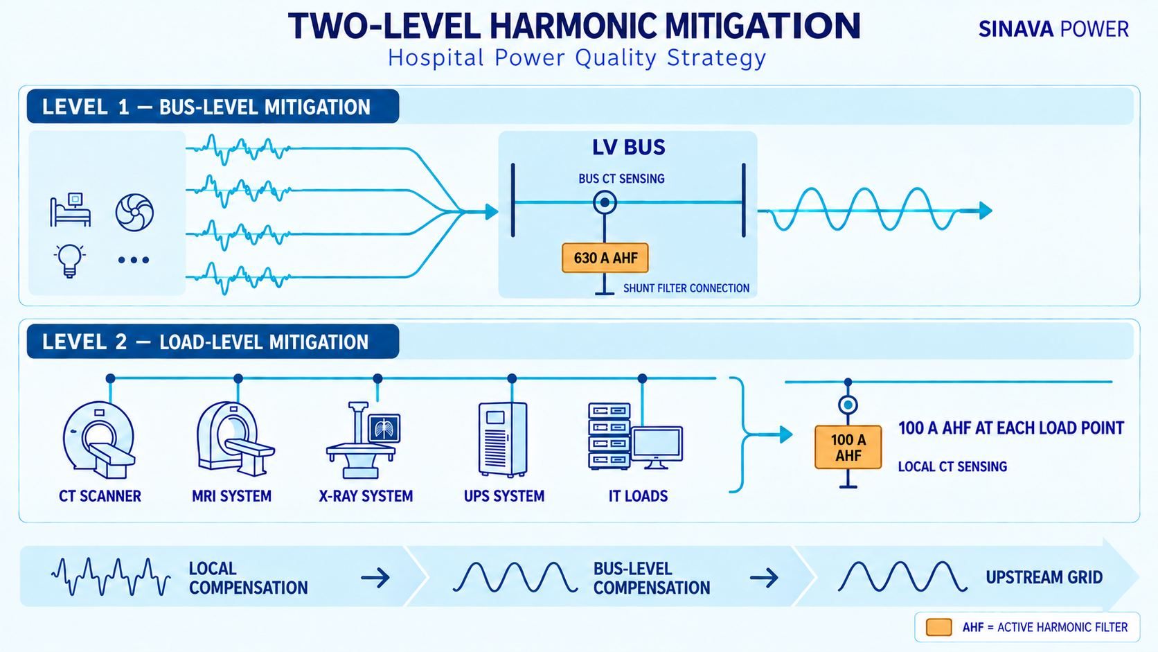
Figure 3. Two-level hospital power quality strategy: bus-level mitigation (630 A) and load-level mitigation (100 A).
7. Independent Treatment of the Radiation Busbar
The radiation system requires special consideration in the AHF configuration.
Medical imaging equipment such as CT and X-ray machines behaves differently from ordinary building loads: their rapid power changes and power-electronic load characteristics can cause significant voltage disturbances and current distortion.
Because the radiation-related equipment is fed from an independent busbar, this project did not mix it with other critical medical loads. Instead, dedicated 630 A AHFs were configured for the radiology busbar according to its actual load and harmonic levels.
For large hospitals with complex distribution structures, this zoned management by functional busbar has good engineering adaptability.
8. Solution Summary
The project ultimately delivers a hierarchical harmonic mitigation system spanning two levels:
The two AHF levels are not a simple capacity superposition — they correspond to different electrical levels of the hospital distribution system. The core design concept flows as:
Load-level harmonic mitigation → Bus-level harmonic mitigation → Upstream power quality control
For large hospitals with independent radiation busbars, critical medical loads, and large populations of UPS and power-electronic equipment, the approach of on-site treatment of critical loads + centralized treatment of distribution busbars matches the AHF installation positions to the actual generation and propagation paths of harmonics.
The same layered power quality management approach can also serve as a design reference for other complex LV systems — data centers, airports, and large public buildings.
The final AHF capacity and installation positions should always be determined from on-site power quality measurements, the hospital's actual single-line diagram, load calculations, and the applicable electrical and supply standards of the project location.
FAQ
Q1. What does an active harmonic filter (AHF) do in a hospital power distribution system?
An AHF measures the harmonic current on its feeder or busbar in real time and injects an equal-and-opposite compensating current, keeping the total harmonic distortion at that point low. In hospitals it protects sensitive medical equipment from distortion caused by UPS systems, imaging equipment (CT/MRI/X-ray), variable-frequency drives, IT loads, and LED lighting.
Q2. Why do hospitals need two levels of harmonic mitigation — 630 A and 100 A?
Hospital harmonics occur at two levels simultaneously: locally, near large nonlinear medical equipment, and collectively, where many loads converge on a busbar. A two-level scheme treats each harmonic at its source (100 A AHFs near critical loads) and mops up the combined distortion at the busbar (630 A AHFs), which is more effective than one large central filter.
Q3. How is AHF capacity selected — what does 630 A mean?
The rating (e.g. 630 A) is the maximum compensating current the AHF can output, not the load current of the busbar. Actual sizing starts from on-site power quality measurements of the harmonic current in each distribution area, plus margin for load growth.
Q4. Why is the radiology (imaging) busbar treated by a separate AHF?
CT, X-ray, and other imaging equipment produce steep power fluctuations and strong nonlinear currents. In this project the radiation loads are fed from an independent busbar, so a dedicated group of 630 A AHFs was configured for it instead of mixing it with other critical loads — preventing cross-coupling between imaging disturbances and other medical equipment.
Q5. Where should AHFs be installed in hospital LV distribution?
Follow the harmonic path: install load-level AHFs (e.g. 100 A wall-mounted modules) as close as possible to critical nonlinear equipment, and bus-level AHFs (e.g. 630 A cabinets) at the LV incoming lines and main functional busbars where harmonics converge. Final positions should follow the single-line diagram and on-site measurements.
About SINAVA POWER : SINAVA POWER provides power quality solutions for hospitals, data centers, and industrial facilities, including active harmonic filters (AHF), static var generators (SVG), and power monitoring systems — from on-site measurement and capacity design to installation and commissioning.
Contact our engineering team | Related product: Active Harmonic Filter (AHF)



Please leave us your messages and feedback, our sales engineers are always right beside you.

