Multi-circuit power meter


Multi-channel power meter
Multi channel power meter provides a compact and robust measurement solution; It can achieve reliable monitoring of commercial building electrical or industrial loads at a lower single point installation cost through sub metering. Single phase circuits can support up to 18 channels, while three-phase circuits can support up to 6 channels.
This device can perform real-time metering, measure energy consumption and power generation, support multi rate time of use (TOU) billing, and monitor power quality. It offers multiple advanced communication options, including Modbus via RS485, Ethernet interface, and various input/output communication combination options, enabling extensive and reliable data exchange.
 Working conditions
-Power supply
AC/DC: 90–240 V, 50/60 Hz;
Maximum power consumption <5 W
- Work environment:
Temperature: -20 ° C~+60 ° C
Humidity: 20%~95% RH (without condensation)
- Storage environment
Temperature: -25 ° C to+70 ° C
Humidity: 20% to 95% RH (non condensing)
 Input
Input
|
Current |
Range: 0–5 A (Optional: 1 A, 5 A, 100 mA) |
|
voltage |
Range: 0–480 V L-L (CATIII-300 V) |
|
frequency |
50/60Hz |
|
current overload |
Can operate continuously at 1.2 times the rated value; can operate for 5 seconds at 10 times the rated value. |
|
Voltage overload |
Operate at twice the rated value for 30 seconds |
Accuracy
|
Parameter |
Accuracy |
A |
B |
C |
Total |
|
voltage Current active power reactive power apparent output power factor Active power energy Reactive power frequency |
0.2 0.2 0.5s 0.5s 0.5s 0.5s 0.5s 1.0 0.1 |
V1 A1 W1 var1 VA1 PF1
|
V2 A2 W2 var2 VA2 PF2
|
V3 A3 W3 var3 VA3 PF3
|
W var VA PF Wh varh Hz |
|
Function |
Parameter |
|
|
|
Real-time parameters |
voltage |
Ua, Ub, Uc / Uab, Ubc, Uca |
● |
|
Current |
Each channel/phase |
● |
|
|
power |
Each channel/phase |
● |
|
|
reactive power |
Each channel/phase |
● |
|
|
apparent output |
Each channel/phase |
● |
|
|
power factor |
Each channel/phase |
● |
|
|
frequency |
Each channel/phase |
● |
|
|
electric energy |
Active power + |
Each channel |
● |
|
Reactive power + |
Each channel |
● |
|
|
Active power- |
Each channel |
● |
|
|
Reactive power- |
Each channel |
● |
|
|
Time-of-Use Electricity Pricing |
4 pricing plans, 12 sub-sessions |
○ |
|
|
Power Quality |
total harmonic distortion |
UTHD, UTOHD, UTEHD, UTHFF, UCF ITHD, ITOHD, ITEHD, IKF |
○ |
|
Single harmonic |
2nd-31st |
○ |
|
|
Voltage imbalance |
/ |
○ |
|
|
Current imbalance |
/ |
○ |
|
|
Demand recording |
Demand record for the past three months |
○ |
|
|
voltage deviation |
/ |
○ |
|
|
report to the police |
Virtual Alarm |
5 alarm triggers |
○ |
|
I/Omodule |
1-channel pulse output |
Default value: 5000 pulses/kWh VCC<48V,Iz<50mA |
○ |
|
6-channel discrete input |
Open-circuit resistance <500 Ω; closed-circuit resistance> 100 kΩ |
● |
|
|
communication |
RS485 interface |
RS485,Modbus-RTU |
● |
Note: "●" indicates standard functionality; "○" indicates optional functionality;
|
Terminal |
Explaination |
|
L/ N |
Auxiliary Input: 85–265 Vac/DC |
|
Ua/ Ub/ Uc/ Un |
A, B, C phase and neutral line voltage input |
|
Metering 1-6 |
6-channel current input |
|
C |
Public terminal |
|
D1-D6 |
6 Relay Input Ports |
|
A B |
RS485 communication interface |
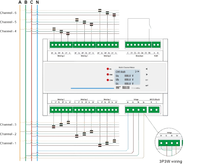
Note: When using the 3P3W wiring configuration, Ub and Un must be externally short-circuited as shown in the diagram; otherwise, the displayed voltage will be incorrect.
Please leave us your messages and feedback, our sales engineers are always right beside you.

