MCCB


MCCB Molded Case Circuit Breaker
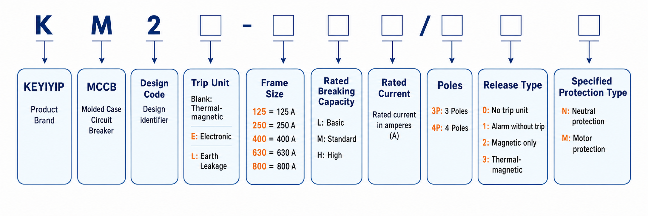
In a AC 50 Hz circuit, KM2 Mccb Molded Case Circuit Breaker can perform well from 16A to 800A up to 800V. The overload, short-circuit and undervoltage releases are designed for the protection of distribution system and motors. Eco-friendly materials are used in KM2. As a Circuit Breaker Manufacturer, SINAVA offers circuit protection solutions for low-voltage electrical distribution. Contact us for product details, technical support, and tailored solutions for your project needs.
Number of poles: 3P, 4P
Applicable category: A
Rated current (In): 63A-630A
Rated operate voltage (Ue):AC400V/AC690V
Rated insulation voltage (Ui): AC800V
Rated impulse withstand voltage (Uimp): 8kV
Type of tripping unit: thermomagnetic
Ambient Temperature: -5℃ ~ 55℃
Breaking capacity (AC400V):
L:Icu=35kA, AC400V, Ics=100%Icu
M:Icu=50kA, AC400V, Ics=100%Icu
H:Icu=65kA, AC400V, Ics=100%Icu
Breaking capacity (AC690V):
M/H:Icu=10kA, Ics=100%Icu
M/H:Icu=15kA, Ics=100%Icu In=630A
Conform to the standard: IEC/EN60947-2 GB/T14048.2
Certificate: CCC CE CB
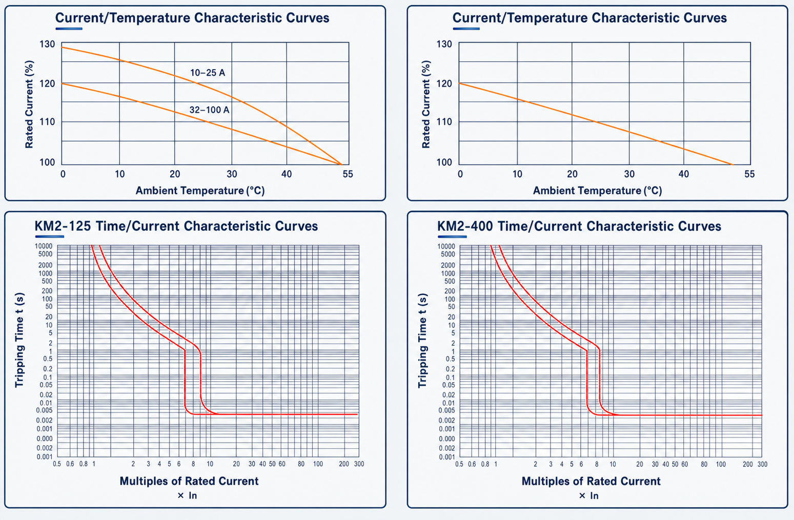
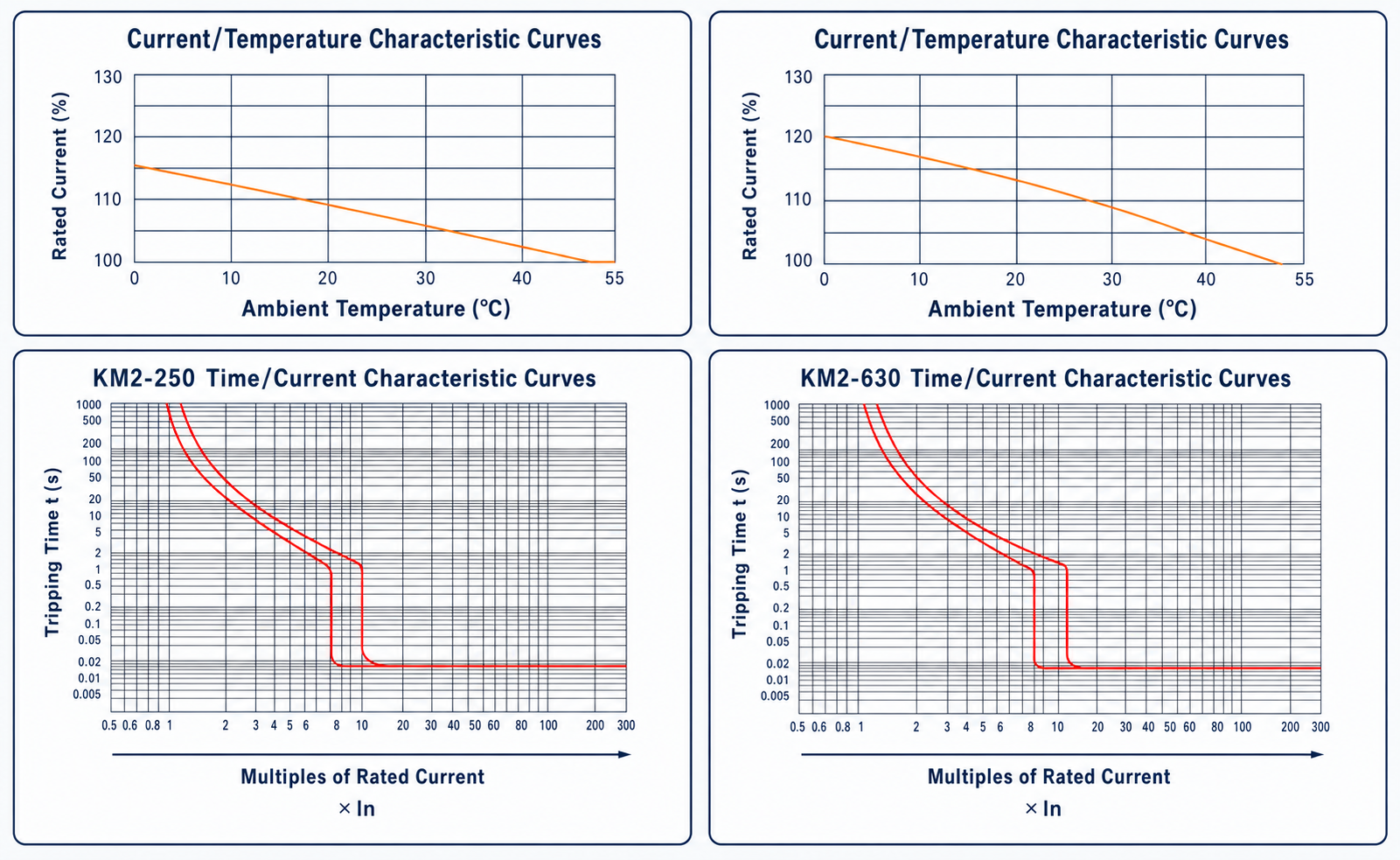
 KM2 Operating Characteristics
Thermal-magnetic Tripping
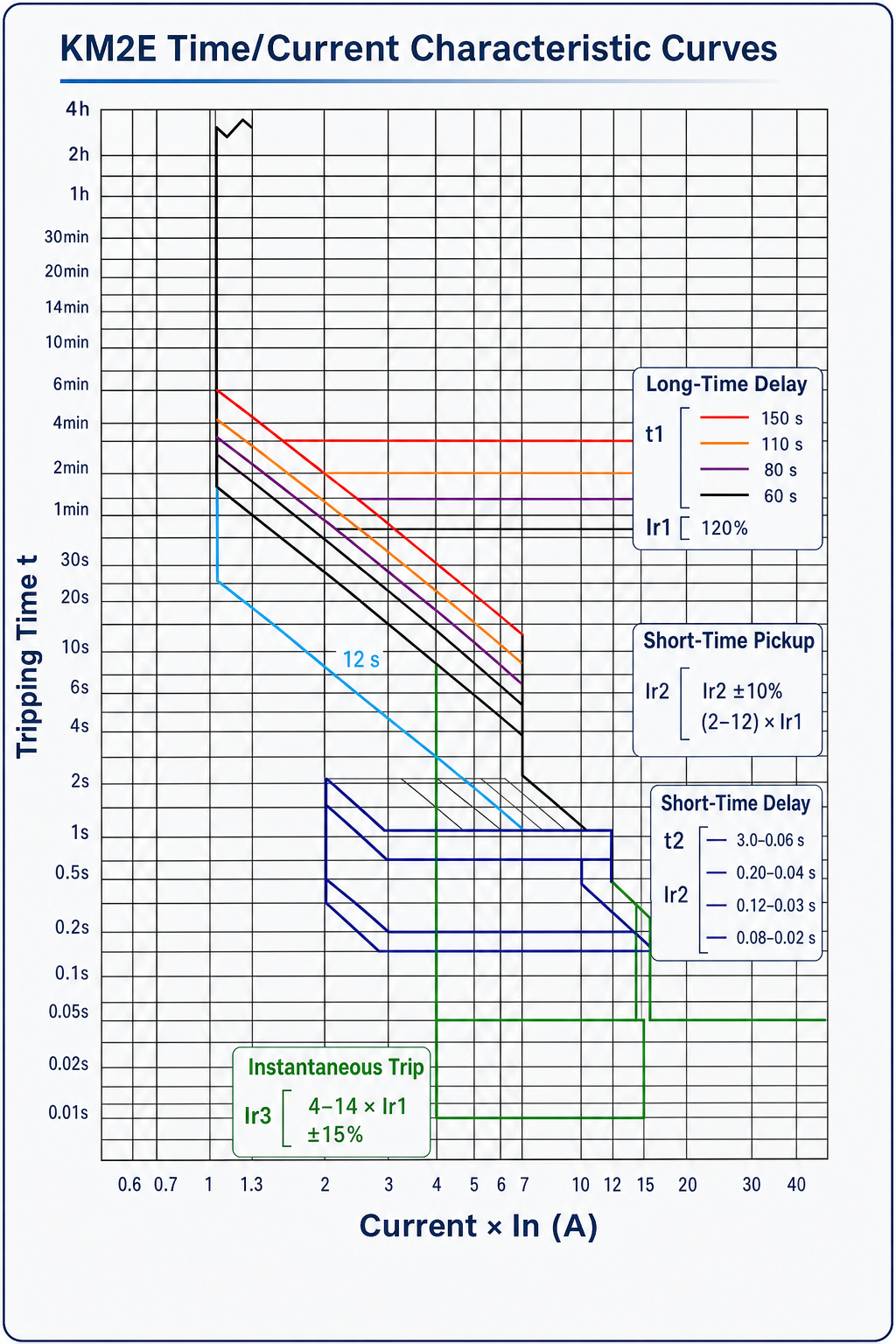
 KM2E Tripping Characteristics
Adjustable Setting
1. Overload Current setting (Ir1)
2. Overload Long-Delay Time (t1)
3. Short-circuit Current setting (Ir2)
4. Short-circuit Short-Delay Time (t2)
5. Instantaneous Trip Current setting (Ir3)
6. Ground fault trip Current setting (Ir4)
7. Test Plug
8. Indicator - Ready to trip
9. Indicator - Overload Pre-alarm (I>0.8xIr)
10. Indicator - Overload (I> 1.05xIr)
| Protective function | Symbol | Setting range | |
| Long time-delay trip | Pick-up current(A) | Ir1 | In=32A: 16 20 25 32 In =63A: 32 36 40 45 50 55 60 63 In =125A:63 65 70 75 80 85 90 95 100125 In =250A: 100 125 140 160 180 200 225 250 In =400A: 200 225 250 280 315 350 400 In =630A: 400 420 440 460 480 500 560600630 In =800A: 6 630640660 680700 720 740760780800 *Non tripping at not more than [lr1]x1.05 *Tripping within 2hours between [ir1]x1.05 and [lr1]x1.3 *Tripping within 1hour between [lr¹]×1.3 and [Ir¹]x2 |
| Time-delay (s) | t1 | (12-60-100-150)(sec) at [Ir1]x2'" *Motor type: (0.93-4.63-6.17-7.72-11.6)(sec) at 720% of Ir1 (21.3-107-142-178-267)(sec) at150% of Ir1 Time-delay setting tolerance: ±20% |
|
| Short time-delay trip | Pick-up current(A) | Ir2 | [Ir1]x(2~12)(2-2.5-3-4-5-6-7-8-10-12) *Current setting tolerance: ±10% |
| Time-delay(s) | t2 | (0.06-0.1-0.2-0.3)(sec) *Time-delay setting tolerance:±20% |
|
| Instantaneous trip | Pick-up current(A) | Ir3 | [Ir1]x(4~14)(OFF-4-6-7-8-9-10-11-12-14) ²) *Current setting tolerance:±15% |
| Ground fault trip | Pick-up current (A) | Ir4 | [Ir1]x(OFF-0.3-0.4-0.5-0.6-0.7-0.8) ③ *Current setting tolerance:±10% |
| (1)For KM2E-125,250, t¹ setting: (OFF-12-60-80-100)(sec) at [lr1]x2 | |||
| (2)For KM2E-125,250, Ir3 setting: (OFF-4-6-7-8-10-11-12-13-14) | |||
| (3)For KM2E-125,250, Ir4 setting: (OFF-0.4-0.5-0.6-0.7-0.8) | |||
| Model | KM2-125 | KM2-250 | KM2-400 | KM2-630 | KM2E-800 | ||||||||
| Breaking Capacity Type | X | L | M | L | M | L | M | M | H | M | H | ||
| Rated Current In(A) | 16,20,25,32,40,50,63,80,100,125 | 100,125,150,160,180,200,225,250 | 250,300,350,400 | 400,500,630 | 400~800 | ||||||||
| Poles | 3/4 | 3/4 | 3/4 | 3/4 | 3/4 | ||||||||
| Rated Insulation Voltage Ui(V) | AC 800 | AC 800 | AC 800 | AC 800 | AC 1000 | ||||||||
| Rated Impulse Withstand Voltage Uimp(V) | 8000 | 8000 | 8000 | 8000 | 8000 | ||||||||
| Rated Service Voltage Ue(V) | AC 400/690 | AC 400/690 | AC 400/690 | AC 400/690 | AC 400/690 | ||||||||
| Rated Ultimate Short-Circuit Breaking Capacity Icu(kA) |
AC400 | 25 | 35 | 50 | 35 | 50 | 35 | 50 | 50 | 65 | 50 | 65 | |
| AC690 | - | 10 | 10 | 15 | 15 | 15 | 20 | ||||||
| Rated Service Short-Circuit Breaking Capacity Ics(kA) |
AC400 | 25 | 35 | 50 | 35 | 50 | 35 | 50 | 50 | 65 | 50 | 65 | |
| AC690 | - | 10 | 10 | 15 | 15 | 15 | 20 | ||||||
| Electrical Life(cycles) | AC400 | 8000 | 7500 | 7500 | 7500 | 7500 | |||||||
| AC690 | 1500 | 1500 | 1500 | 1500 | 500 | ||||||||
| Mechanical Life(cycles) | 20000 | 10000 | 10000 | 10000 | 10000 | ||||||||
| Dimension (mm) |
W(3/4) | 75/100 | 92/122 | 107/142 | 150/198 | 182/240 | 210/280 | ||||||
| L | 130 | 150 | 165 | 257 | 270 | 280 | |||||||
| H | 84 | 83 | 103 | 107 | 110 | 115.5 | |||||||
| Shunt Trip | O | O | O | O | O | ||||||||
| Undervoltage Release | O | O | O | O | O | ||||||||
| Auxiliary Switch | O | O | O | O | O | ||||||||
| Alarm Switch | O | O | O | O | O | ||||||||
| Motorized Operation Mechanism | O | O | O | O | O | ||||||||
| Operating Rotary Handle | O | O | O | O | O | ||||||||
Please leave us your messages and feedback, our sales engineers are always right beside you.

