Energy meter


The single-phase din rail-mounted energy meter is manufactured using large-scale integrated circuits, digital sampling and processing technology, and SMT processes. The overall design incorporates multiple anti-interference techniques, making it suitable for time-of-use metering of single-phase AC active power with a rated frequency of 50Hz, thereby better balancing grid load.
This energy meter features a Chinese-language LCD display, with combined active power (forward + reverse) metering capabilities, data storage, remote disconnection/reenabling functions, event recording, and 485 communication capabilities.
 Parameters
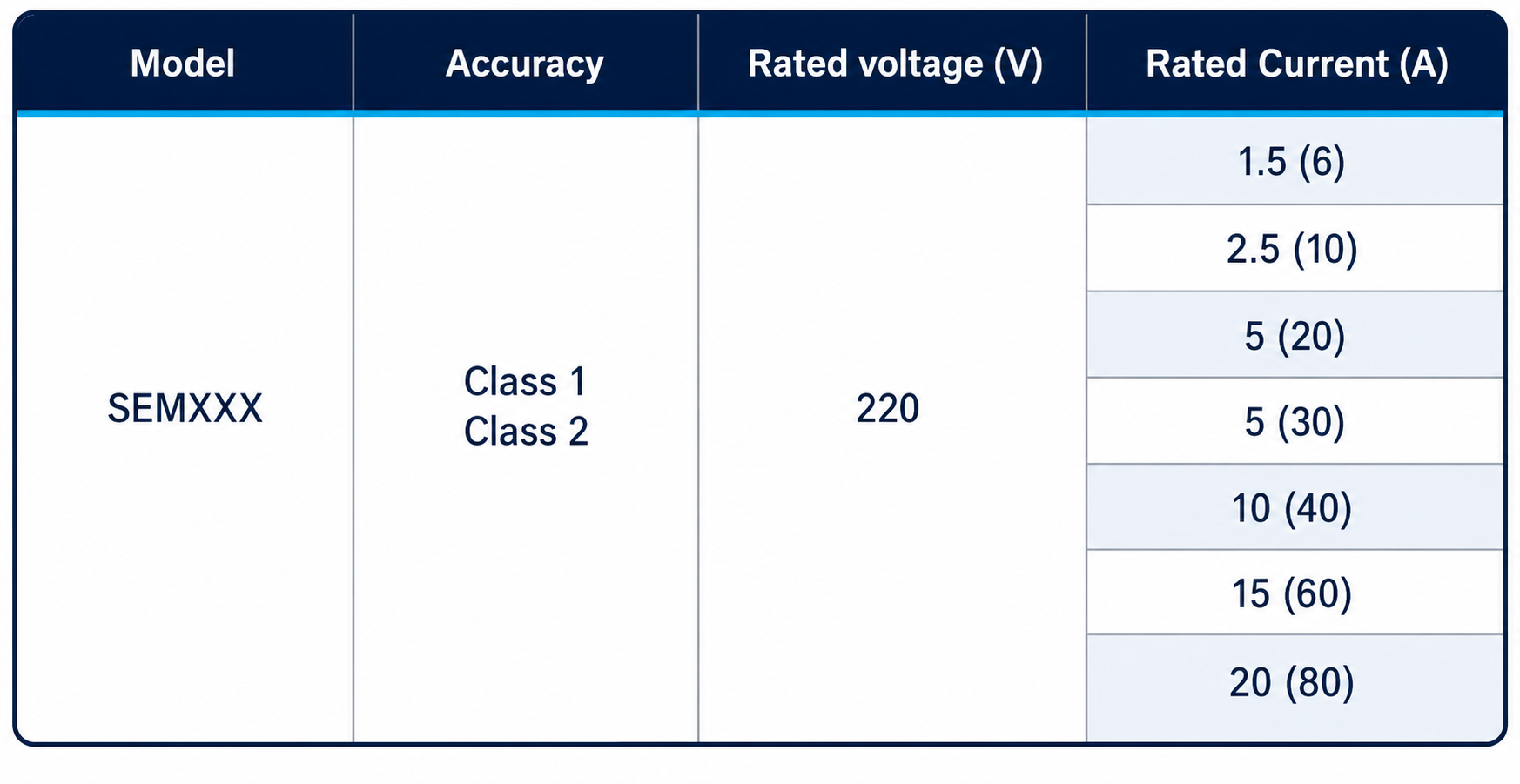
 Technical
1. Start up: With power factor of 1.0 and current of 0.4% lb, the energy meter has pulse output and continuous recording within the specified time.
2. Stealth: With anti creep logic design, when the electric energy meter applies 115% of the reference voltage and there is no current in the current circuit, the test output of the electric energy meter does not generate more than one pulse.
3. Communication baud rate: The default baud rate for RS485 interface is 2400bit/s.
4. The communication protocol of the electric energy meter complies with the DL/T645 protocol. Modbus RTU protocol.
5. Design lifespan: Under normal working conditions, the average lifespan of the electric energy meter shall not be less than 10 years
6. Power consumption: Voltage line power consumption ≤ 1.5W/10VA, current line power consumption ≤ 1VA; voltage line power consumption ≤ 3W/12VA in communication state.
 Environment
- Environmental conditions: The specified working temperature range is -25 ° C~+60 ° C;
- The working limit temperature range is -40 ℃~+70 ℃;
- Annual average relative humidity:<75%;
- The atmospheric pressure ranges from 6.0kPa to 106.0kPa (at an altitude of 4000m and below).
 Accuracy
Voltage range:
- The specified working voltage range is 0.9Un~1.1Un;
- Extended working voltage range: 0.8Un~1.15Un;
- Maximum operating voltage range: 0.0Un~1.15Un.
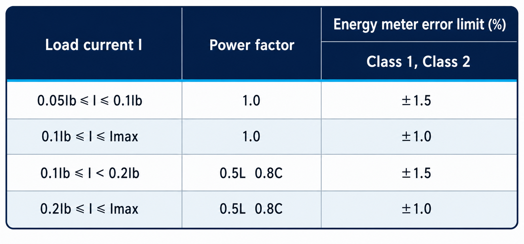
Percentage error limit: Under the specified reference conditions, the percentage error of the electric energy meter shall not exceed the provisions in the following table.
Installation precautions and methods
1. The energy meter can be installed and used after passing the inspection and being sealed with a lead seal before leaving the factory. Energy meters without lead seals or stored for too long should be re inspected by relevant departments before installation and use.
2. If damage is found to the inner packaging or outer shell of the electric energy meter when it is removed from the original packaging box, do not install or power on the meter. Please contact our technical service department.
3. Experienced electricians or professionals are required to install the energy meter and ensure that they have read this manual thoroughly.
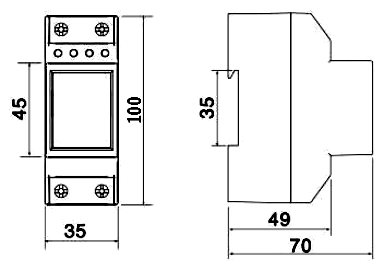
4. The electric energy meter should be installed in a ventilated and dry indoor area, using a 35mm DIN standard rail installation. The base plate for installing the electric energy meter should be fixed on a sturdy, fire-resistant, and vibration resistant wall.
5. In places with pollution and potential damage to the mechanism, the energy meter should be installed in a protective cabinet.
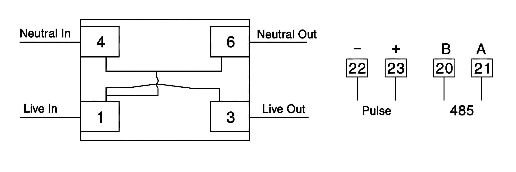
6. When installing wiring, follow the wiring diagram on the terminal cover of the electric energy meter or the corresponding wiring diagram in this manual. It is best to adapt to the introduction of multiple copper wires to avoid abnormal operation or burning of the electric energy meter due to poor contact.
When the electricity meter is correctly connected to the grid, the power indicator light of the meter should be constantly on.
Instructions for use
1. When using an electric energy meter in areas with frequent lightning strikes, lightning protection measures should be taken to avoid damaging the meter due to lightning strikes.
2. The load capacity of the electric energy meter is between 0.05lb~Imax (direct connection type) or 0.02lb~lmax (through transformer connection type). Exceeding this load capacity will result in inaccurate measurement of the electric energy meter or burning of the current coil due to heating.
3. When an electric energy meter is used with a transformer, that is, an electric energy meter connected through a current transformer must multiply the reading of its electric energy by the transformer multiplier to obtain the actual electricity consumption.
4. Data display: 8-bit (6+2) LCD displays the total active power consumption
5. Pulse indication: When the pulse indicator light is on, it indicates the detection of a power pulse (when there is a sampling signal, the pulse indicator light is on for about 80ms).
6. Indicator light function: Detected power pulse (when there is a sampling signal, the pulse indicator light lights up for about 80ms); When the electric meter relay is closed, the indicator light remains on as an alarm light. After closing, the alarm light cancels the alarm and acts as a pulse light.
Please leave us your messages and feedback, our sales engineers are always right beside you.


